
How Timber Frame Structures Are Engineered: Load Ratings, Wind Loads & Stamped Plans
Timber frame structures are engineered by calculating every load the frame will carry, including its own weight, snow, occupants, and wind, then sizing each beam, post, and joint to carry those loads down to the foundation, using the National Design Specification (NDS) for Wood Construction and the wind and snow data for the site. Where the project or the jurisdiction requires it, a licensed professional engineer reviews and seals those calculations as a stamped drawing set.
Massive beams look strong, and that look is easy to mistake for proof. Timber frame engineering is the opposite of a guess: it’s a documented chain of calculations, from the snow sitting on the roof today to the wind gust hitting the gable end in a storm forty years from now. If a builder can’t show you the load ratings, the wind and structural assumptions, and the drawings behind the word “strong,” you’re buying a feeling, not a structure.
Key Takeaways
- A timber frame carries its loads through a few large posts and beams, so each member and joint is sized by calculation.
- Engineers account for dead load, live load, and environmental loads such as snow, wind, and seismic forces, then combine them as the code requires.
- Wind design depends on the site’s design wind speed and exposure category, not one national number.
- Traditional joinery works by keeping connections in compression wherever possible.
- A stamped drawing is a legal certification by a licensed engineer, required when the project or jurisdiction calls for one.
What Timber Frame Engineering Actually Means (and How It Compares to Standard Framing)
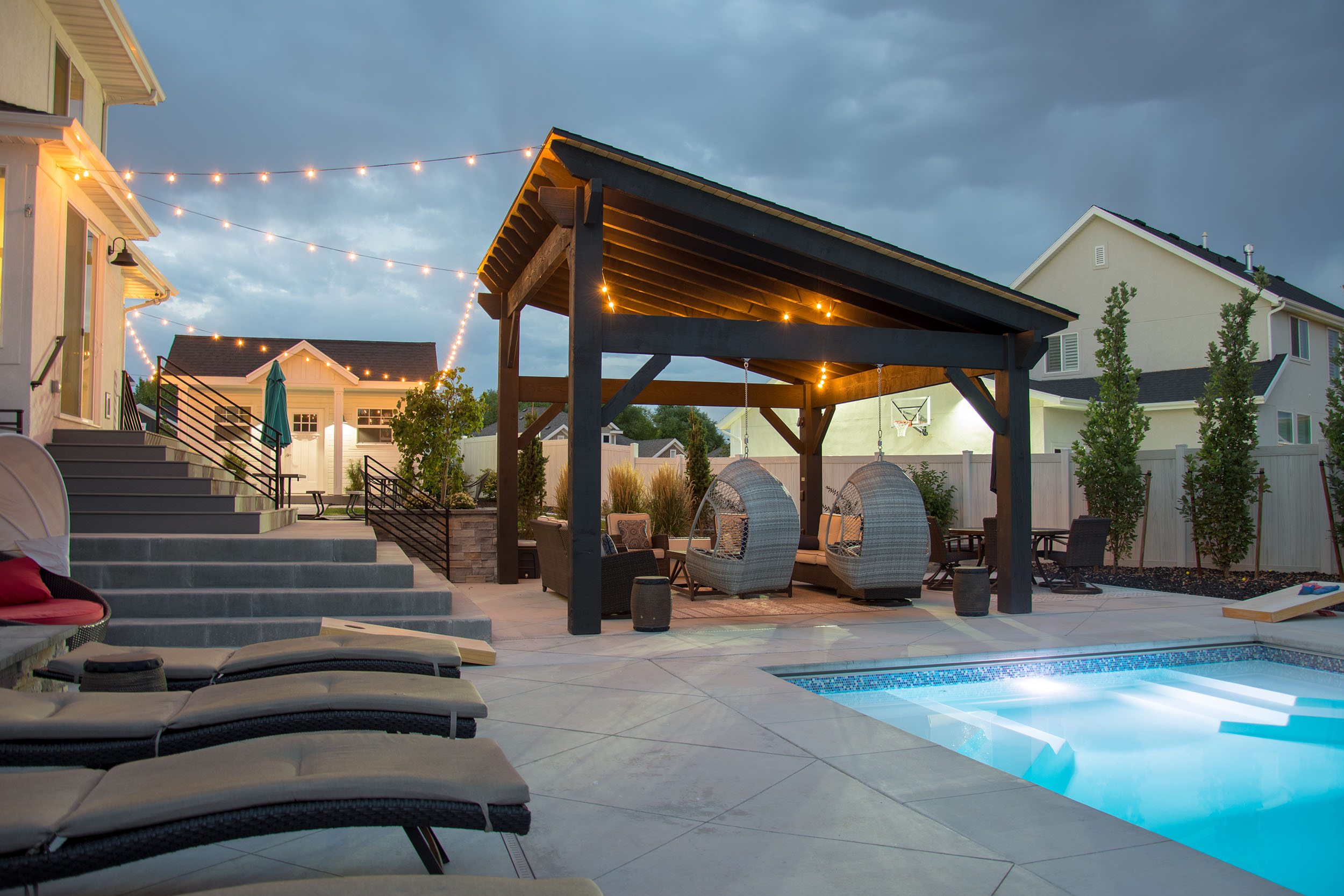
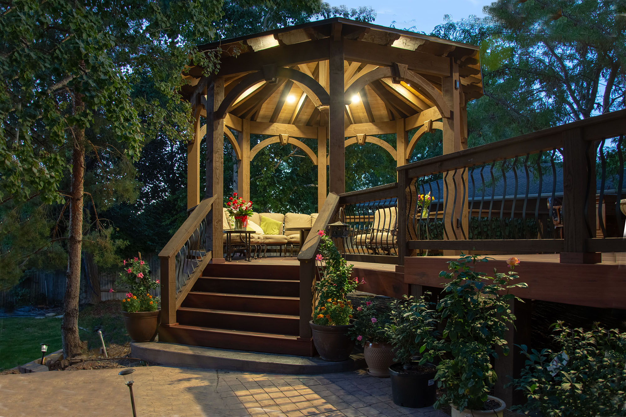
A timber frame is a post-and-beam structural system in which large timbers, not repetitive studs, carry the building’s loads through engineered joinery rather than nailed connections. A timber structural frame is that skeleton of posts, beams, braces, and rafters, whether it holds up a house, a barn, or a backyard pavilion that shelters a patio from sun and snow.
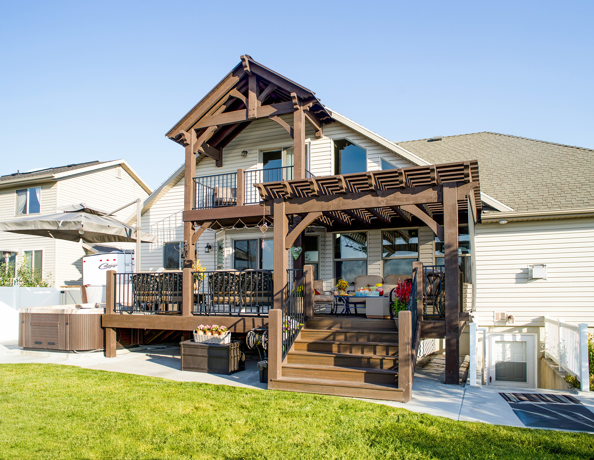
An exposed frame changes the engineering problem. Every beam, post, and joint is visible and load-bearing, so there’s no drywall hiding an oversized connector or a doubled-up stud. The joint has to carry the load and look right doing it.
Timber Frame vs. Light-Frame (“Stick-Built”) Construction: What Changes Structurally
|
Factor |
Light-Frame (“Stick-Built”) |
Timber Frame |
|---|---|---|
|
Load path |
Distributed across many small studs, typically 16 to 24 inches on center |
Concentrated through fewer, larger posts and beams |
|
Primary connections |
Nails, metal hangers, and sheathing |
Mortise-and-tenon joinery, pegs, and engineered hardware |
|
Lateral resistance |
Sheathed shear walls |
Knee braces, diaphragms, engineered bracing, or shear panels |
|
Span capability |
Limited without engineered lumber such as I-joists and LVL |
Suited to open spans with larger timber sections |
|
Engineering scrutiny |
Often covered by prescriptive code tables |
Frequently requires project-specific engineering and a stamped set |
Tip: If a builder says a timber frame “doesn’t need engineering because it’s prescriptive,” treat that as a red flag. The International Residential Code’s wall framing tables are written for studs and joists; heavy timber spans and joinery generally fall outside them and call for engineered design.
Load Ratings: How Engineers Size Every Beam Before It’s Cut
Engineers account for several kinds of loads. Dead load is the permanent weight of the structure itself: timbers, roofing, and fixed components. Live load covers changing loads such as occupants and movable items. Environmental loads such as snow, wind, and seismic forces are calculated separately, then combined in the load combinations required by the applicable code.
Those loads follow a load path: roof surface to rafters and purlins, rafters to beams, beams to posts, and posts to the foundation. Every post needs a continuous path to solid bearing. A weak or inadequately designed connection can interrupt that path and become the point where performance is compromised.
|
Load Type |
Example |
Why It Matters |
|---|---|---|
|
Dead load |
Weight of timber, roofing, and fixtures |
Constant; the baseline every beam carries regardless of weather |
|
Snow load |
Roof snow load, which varies by region and roof pitch |
Can exceed dead load in northern and mountain climates and often drives beam depth |
|
Live load (occupancy) |
People, furniture, and equipment on a deck or floor |
Governs floor and deck framing in habitable timber structures |
|
Wind load (uplift) |
Wind trying to lift the roof off the frame |
Requires uplift connections, not just gravity framing |
Beam sizing isn’t a rule of thumb. Engineers run these loads through allowable stress calculations in the American Wood Council’s NDS, using the reference design values for the specific species and grade of timber. That’s why a Douglas Fir beam and a similarly sized pine beam aren’t interchangeable on paper even if they look the same.
Snow is a good example of why site-specific engineering matters. Ground snow load can change dramatically with location, elevation, and local amendments, and engineers use those site conditions along with roof geometry and the applicable code provisions to determine the design snow load the structure must resist. Western Timber Frame™ designs each structure for the snow and wind loads at its install address, which is why two identical structures can be engineered differently in two towns.
How Do Timber Frame Buildings Actually Stay Standing?
Gravity loads travel down through the frame like water finding the lowest point: roof to rafters, rafters to beams, beams to posts, posts to the ground. Sideways loads from wind are caught by bracing before they can rack the frame out of square. The system only works if every connection along that path is accounted for, and that continuous accounting is a central part of an engineered load path.
Wind Loads: Engineering for What You Can’t See Coming
Gravity loads are predictable. Lateral loads, the forces that push a structure sideways, are the ones that determine bracing and connection design. Wind design starts with the site’s design wind speed from ASCE 7, the standard the building codes reference, which anyone can look up by address with the ASCE Hazard Tool.
Wind speed alone isn’t enough. ASCE 7 also assigns an exposure category based on the terrain around the structure:
- Exposure B: urban, suburban, or wooded areas with many closely spaced obstructions.
- Exposure C: open terrain with scattered obstructions, such as farmland and open fields.
- Exposure D: flat, unobstructed areas and shorelines facing open water.
The same structure needs a stronger connection package in Exposure D than in Exposure B at the same wind speed. The label is shorthand; the actual terrain around the site is what the engineer evaluates.
Earthquakes are the other half of lateral design. Seismic design treats the structure’s own mass as the force trying to move it sideways, and that force is resisted by the same bracing and diaphragm systems that resist wind, sized to the site’s seismic design category.
Western Timber Frame’s standard engineering starts at 115 mph, and a site that requires a higher design wind speed is engineered to that requirement. The important number for any individual project is the requirement for that site.
Worth knowing: A wind load isn’t one number. It’s pressure and suction acting on different faces of the structure at the same time, which is why corner and edge connections are typically engineered heavier than those in the middle of a wall or roof.
Mortise-and-Tenon Joinery: How Traditional Connections Distribute Load
Wood is strong in compression (pushing) and much weaker in tension perpendicular to the grain (pulling apart). Nearly every timber joint design is a strategy for keeping connections in compression wherever possible.
- The peg has a real job. A wooden peg through a mortise-and-tenon joint resists the tenon withdrawing under load and transfers shear between the two members, while still letting the joint move slightly as the timber swells and shrinks with the seasons.
- Housed joints share the work. In a housed joint, the full width of one timber seats into a shallow notch in another, so compressive load transfers directly through wood-on-wood bearing and the peg isn’t carrying it alone.
Traditional timber framing often secures a mortise-and-tenon joint with a wooden peg. Western Timber Frame’s patented Dovetail Difference® joinery (U.S. Patent No. 9,797,149 B2) takes another route to the same tension-versus-compression problem: a CNC-cut dovetail with interlocking wood-to-wood geometry locks beam to post, so exposed metal brackets aren’t what hold the primary joint together.
Engineered Wood Products: Where Glulam and CLT Fit Into Modern Timber Engineering
|
Factor |
What It Is |
Structural Advantage |
|---|---|---|
|
Solid-sawn timber |
A single piece of timber cut from the log and used with traditional joinery |
The authentic timber frame look; limited in length and section by tree size and grade |
|
Glulam (glue-laminated timber) |
Layers of lumber bonded with structural adhesive, grain running the same direction |
Longer spans, dimensional stability, and curved profiles |
|
CLT (cross-laminated timber) |
Layers of lumber glued at 90 degrees to each other into large panels |
Strength in two directions; used for floors, walls, and roof diaphragms in mass timber buildings |
Traditional timber framing and modern mass timber sit on a spectrum rather than competing with each other. A hand-joined post-and-beam frame and a CLT panel system solve different problems: one is a visible, crafted structure, the other forms large panelized floors and walls for commercial buildings. Plenty of projects use both, and most residential timber frame work still centers on solid-sawn timber and glulam rather than CLT panels.
Fire Safety and Resistance Engineering in Heavy Timber Structures
Large timber sections perform predictably in fire. The surface chars at a known, testable rate, and that char layer insulates the structural core underneath. The American Wood Council’s fire design method uses a nominal char rate of 1.5 inches per hour, and the rate slows as the char layer builds. By that model, a timber loses about 2.6 inches of wood to charring after two hours of fire exposure. As the surface chars, the char layer helps insulate the wood beneath it, and engineers account for that predictable loss of section to determine whether the remaining timber is large enough to carry the required load for a specified fire-resistance period. Western Timber Frame’s breakdown of how mass timber charring works as a fire shield walks through the numbers.
Steel is the useful contrast. Steel doesn’t burn, but it loses strength as it heats, which is why exposed structural steel in buildings usually needs applied fireproofing. A large, char-protected timber gives engineers a slower, more predictable failure mode to design around. The USDA Forest Products Laboratory’s Wood Handbook covers timber fire performance in detail.
Building Codes and Standards: What “Stamped Plans” Actually Require
- The code stack. The International Building Code (IBC) or International Residential Code (IRC) is the legal framework a jurisdiction adopts. The NDS is the technical standard those codes point to for how wood structures are calculated; the IBC’s Chapter 23 is where that connection is made.
- What “stamped” means. A stamped drawing set is a structural drawing set that a licensed Professional Engineer (PE) has reviewed and sealed, certifying that the calculations meet code for that specific project and site. It isn’t a formality; it’s a legal certification tied to that engineer’s license, and it has to come from an engineer licensed in the project’s state.
- When a stamp is required. Most standard stick-framed homes fall under the IRC’s prescriptive tables. Custom timber frame spans, connections, and open floor plans often fall outside those tables and need project-specific engineering. For small accessory structures such as pergolas, requirements vary widely by city: some accept engineered drawings without a seal, others require a stamp. See how engineering and stamped drawings work for pergolas.
Tip for homeowners: Ask to see a sample drawing set before you sign a contract. A real stamped set includes framing plans, connection details, and the engineer’s seal with a license number, not just a rendering.
From 3D Model to Stamped Drawing: The Modern Timber Engineering Workflow
Timber engineering today isn’t done on paper. It’s modeled in purpose-built CAD and BIM software that lets designers and engineers see every joint, cut, and connection before a single timber is milled. The same digital model then drives the CNC equipment that cuts the frame, so what was engineered is what gets built.
The Step-by-Step Engineering Workflow for a Custom Timber Frame Structure
- Concept and load inputs. Site location, roof geometry, and span requirements set the starting loads: snow, wind, seismic, and occupancy.
- 3D structural modeling. The frame is modeled digitally so every post, beam, and joint location is fixed before cutting.
- Member and connection sizing. Each beam, post, and joint is checked against NDS design values for the chosen species and grade.
- Lateral system design. Bracing, shear panels, or moment connections are sized to the site’s wind and seismic loads.
- Drawing production and review. The final calculations and drawings are prepared for permitting. Where the project or jurisdiction requires it, a licensed PE reviews and seals them.
- Permitting and CNC fabrication. The homeowner or builder files the drawing set with the local building department while the frame is precision-cut from the same digital model.
What to Ask Before a Single Timber Is Cut
A load rating comes from calculation. A design wind speed comes from the site, not a marketing department. And a stamped drawing is an engineer’s certification, not a rendering. With that in view, the real question isn’t whether a timber frame can be engineered to last, whether it’s a home or a pavilion built to give your yard shade and shelter for decades. It’s whether the company building yours can show you the math: the loads it used, the design values behind each member, and the connection details that carry it all to the ground. That’s the conversation worth having before a single timber is cut.
Questions About Timber Frame Engineering
Western Timber Frame™ — Payson, Utah | Since 2008 | 7,000+ structures in all 50 states
2026 SBA Manufacturing Award | HGTV Design Excellence Award | 28 Best of State Awards